The concrete wall panel element allows you to easily model, analyze, and design concrete walls for in plane and out of plane loads. Here we will explain how concrete design rules work. For general wall panel information, see the Wall Panels topic. For information on concrete wall design considerations, see the Concrete Wall - Design topic. For concrete wall results interpretation, see the Concrete Wall Results topic.
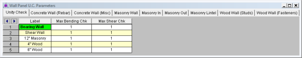
Setting a maximum Bending Check (Axial & Bending) or a maximum Shear Check controls the rebar which the program chooses for the wall design. A value of 0.9 denotes that the program may choose a rebar layout that is at 90% of capacity.
Note:
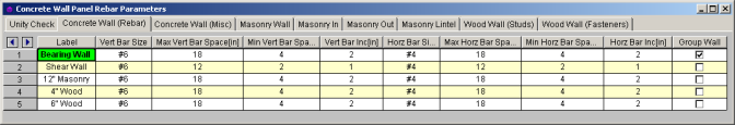
These are the vertical and horizontal bar sizes used for reinforcement of the wall.
Note:
The program will design the reinforcement spacing based on these guidelines. If you want the reinforcement to be at an exact spacing, simply enter that spacing as both the min and max in order to force this spacing.
This is the spacing change increment that the program will use for design. If the maximum spacing does not work, the spacing will drop by this increment and be checked again. The program will work its way down until it reaches a spacing that meets all reinforcement requirements.
For walls that have multiple regions, this checkbox allows you to group the reinforcement for the regions in a wall. Thus, the worst case vertical and horizontal reinforcement spacing will be used for all regions in the wall.
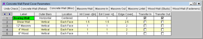
This defines whether the reinforcement mesh has the Horizontal or Vertical bars closest to the face of concrete.
This allows you to locate reinforcement at each face of wall or centered. If the reinforcement is defined as centered then the program places the vertical bar directly at the center of the wall. The horizontal bar is then placed to one side or the other based on the "Outer Bars" designation.
Note:
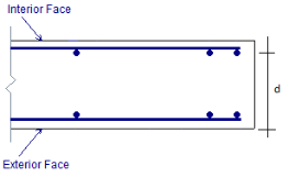
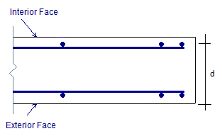
This is the clear cover distance from the interior face of wall to the outer reinforcement. The interior face of the wall is defined by the negative z local axis direction of the wall.
This is the clear cover distance from the exterior face of wall to the outer reinforcement. The exterior face of the wall is defined by the positive z local axis direction of the wall.
This is the "in plane" cover dimension for the outer edges of walls.
These options allow you to transfer loads from regions above and below openings to adjacent full-height regions. Transfer in is for in plane loads and transfer out is for out of plane loads. Here is an image of a wall:
![]()
If either of the Transfer options are turned on for this wall, then any loading in that plane (in plane or out of plane) for regions above and below openings will have their load transferred into the adjacent regions.
![]()
A couple of things to keep in mind with the Transfer options: